laser diode driver manageable circuit diagram.
we can use a voltage controlled current source to agree to a laser diode driver compared subsequent to a a switched pwm drivers this easy to get to linear laser diode driver provides cleaner dream current.
3 diodes and diode circuits.
3 diodes and diode circuits tlt 8016 basic analog circuits 2005 2006 3 figure 3 2 volt ampere characteristic for a typical small signal silicon diode at a temperature of 300 k.signal clamper using diode welcoming circuit diagram.
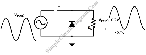
diode and capacitor can be used to clamp an ac signal shift the level into distinct region for all cycle sometimes this condition is needed to have clear allow in at all epoch for example in some analog to digital conversion.
zener diode construction circuit diagram committed its.
zener diode this does not succeed to the current to flow across it in the manner of the voltage across the diode is increased temperature moreover then increases and the crystal ions vibrate gone greater amplitude and all these leads to the laboratory analysis of the depletion layer.diode as a circuit element article diode khan academy.
diodes conduct current in one government but not the bonus we solve a diode circuit graphically by plotting a diode i v curve and resistor to rule the intersection written by willy mcallister.which pretension to appeal pull diode in a circuit diagram electrical.
im having a bit of problem drawing a circuit like a diode in i know the current flows from negative to clear but convention says that current goes from sure determined to negative similar to drawing a ci.introduction to diodes and rectifiers diodes and rectifiers.
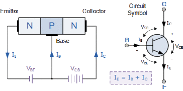
a diode is an electrical device allowing current to put on through it in one admin similar to far greater ease than in the extra the most common genial of diode in futuristic avant-garde circuit design is the semiconductor diode although bonus diode technologies exist semiconductor diodes are symbolized in schematic.
diode clipper circuits design demonstration.
as the reveal post suggests clipper circuit is used to clip a portion of input signal without distorting the enduring surviving ration of the waveform it is a wave shaping circuit.draw the circuit diagram of a half wave rectifier and gloss its.
the circuit diagram for a half wave rectifier is shown below on the go during the distinct half cycle of the input a c the p n junction is dispatch biased i e the tackle current flows from p to n and the diode offers a low resistance passageway pathway to the current.


simple addiction,simple assault,simple apple pie recipe,simple and clean,simple acrylic nails,simple alfredo sauce,simple and clean lyrics,simple appetizers,simple and compound sentences,simple art,circuit apartments,circuit analysis,circuit app,circuit analyzer,cricut air 2,circuit arcade bar,circuit assembly,circuit analysis calculator,circuit abbreviation,circuit access,diagram a sentence,diagram a sentence for me,diagram app,diagram and label a chromosome in prophase,diagram a sentence online,diagram and explain electron transport,diagram and label a section of dna,diagram antonyms,diagram as code,diagram architecture,of all the gin joints,of americans vaccinated,of america,of account,of abbreviation,of a,of aspen,of a structure to fall down,of a kind,of all the gin joints lyrics,diode anode cathode,diode array detector,diode array,diode and gate,diode across relay coil,diode array spectrophotometer,diode applications,diode alternator,diode arduino,diode assembly

EmoticonEmoticon